How to Connect Automatic UPS / Inverter to the Home Supply System?
helvetica, sans-serif" style="font-size: 12pt;">Automatic Inverter / UPS System Connection & Wiring Circuit Diagram
Table of Contents
Introduction to Automatic Inverter / UPS Wiring
Power failure and emergency breakdown may happen any time due to short circuit, damage to electric transmission lines, substations or other parts of the distribution system , storms and other bad weather conditions etc. In this case, emergency generator or battery backup can be used to restored the electric power to the home and other connected appliances. In some case, it is very important to restore the power as soon as possible like in Hospital ICU, military, Intelligence and security systems & offices etc. This is where we use the generator and Inverter / UPS (Uninterruptible Power Supply) system with the help of backup batteries and inverter.
For this purpose, we have to shows an automatic UPS / Inverter system connection and wiring to the home or office supply. We have different tutorials on UPS and Inverters wiring & installations to the home distribution boards such as manual, automatic and inverter / UPS with changeover switches.
Why & Where we Need Auto UPS / Inverter System?
As we have mentioned above that emergency breakdown and power blackout may happen anytime due to a number of reason. In some cases, you may need a continues and uninterruptible power supply to the connected system such as security networks & systems, operation theater & ICU in hospitals, airports, military and intelligence systems and other important electrical networks. In other ordinary cases where you face load-shedding from the power supplier, unavailability of secondary power i.e. generator, solar, wind power etc, low voltages issues, shortage of stored power in the batteries, where you need an uninterruptible power to your home, office, PC, or particular rooms and load points in home or office in case of failure of main power supply. In all those situations, you need an automatic UPS / Inverter wiring connection to the home panel board.
How to Connect a UPS / Inverter to the Home Supply System?
To connect an inverter / UPS to the home electric supply system, follow the steps below:
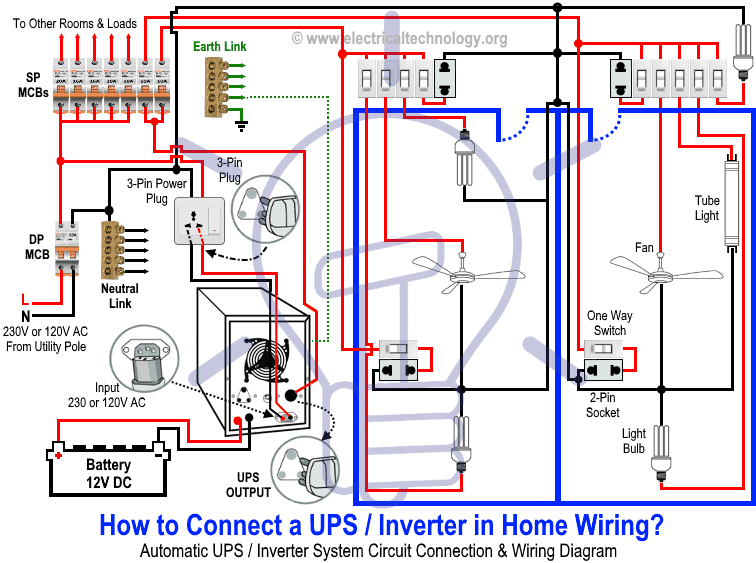
First of all, disconnect those Live (Line) wires of two circuit breakers from the main distribution board which are connected to the main double pole switch of those particular rooms (As shown in Fig) which you want to connect to the automatic supply (in both cases from battery and main utility power without any interruption).
Suppose,
you need to connect only two rooms and their load with UPS automatic
system as shown in fig . You will have to disconnect the live wires of
these rooms from the main power supply distribution board. Now connect
these two live wires (of those specific room which have to be connected
to the UPS System) to the output of UPS through the two single pole MCBs
(separated from the main panel board). Done.
Keep in mind that only the two connected MCBs (and their related and connected load) to the inverter will supply continues power in case of blackout. To charge the Battery via inverter, connect the Inverter / UPS to the outgoing of main double pole (DP) MCB through a 3 Pin Power Plug and 3 Pin Power socket to the main supply.
Note: To be in safe mode, use 6 AWG (7/064″ or 16mm2) cable and wire size to connect the UPS to the main panel board.
Below is a given UPS Inverter connection and wiring diagram to the home supply. The circuit shows that only two rooms of the home are depends on the UPS and Batteries as well as main supply to maintain the uninterruptible power to the connected appliances and load such as lighting points and fans etc and the other loads are fed up by utility power only. Once you get the basic idea of UPS connection, proceed to know how it works in both cases i.e. operation of the circuit when utility power is available and battery backup as secondary power in case of power failure.
Click image to enlarge
Working Principle & Operation of Automatic UPS / Inverter
1. In case, when the utility power supply is not available:
In
case of unavailability of main electric supply, power flow will
continue to the particular rooms / office and appliances connected to
the UPS system and battery where inverter convert the 12V DC system to
Single Phase 230V AC (UK & EU) or 120V AC (US & Canada) voltages
according to the specification and ratings.
The Blue Line shows the power flow in the circuit from battery, UPS and then load points.
Click image to enlarge
UPS / Inverter Wiring & Connection Diagram
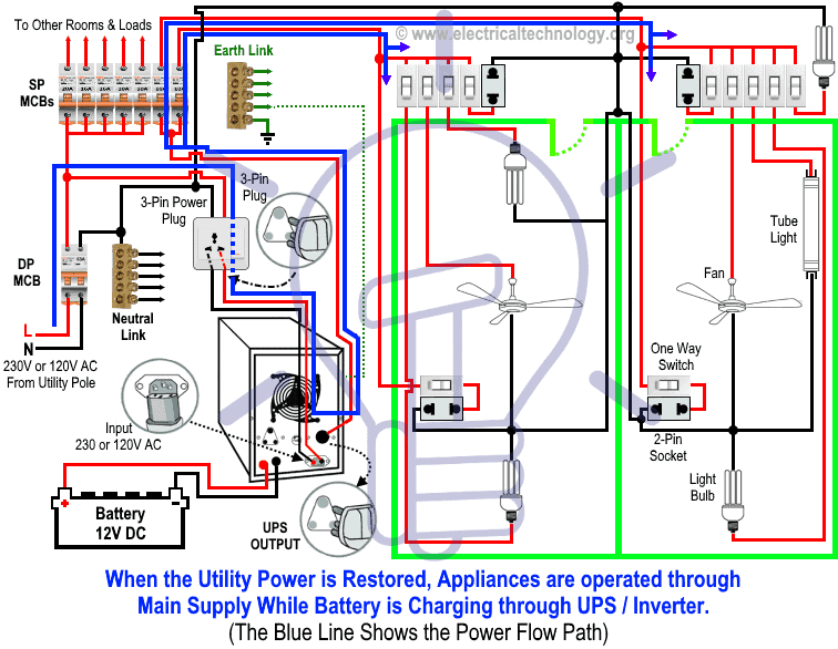
2. In case, when power supply restores from the power house:
In this case, the main electric lines supplies power to the home appliances in particular connected rooms. Keep in mind that UPS / Inverter will start to charge the battery i.e. it will convert the main Single Phase 230V AC (UK & EU) or 120V AC (US & Canada) voltages into 12V DC to charge the battery for backup storage. The Blue Line show the power flow from main distribution board to UPS/Inverter and then load points connected through UPS System.
Click image to enlarge
Wiring Color Code:
We have used Red for Live or Phase , Black for Neutral and Green for Earth Wire in single phase. You may use the specific area codes i.e. IEC – International Electrotechnical Commission (UK, EU etc) or NEC (National Electrical Code [US & Canada] where;
NEC:
Single Phase 120V AC:
Black = Phase or Line, White = Neutral and Green/Yellow = Earth Conductor
IEC:
Single Phase 230V AC:
Brown = Phase or Line, Blue = Neutral and Green = Earth Conductor.
(adsbygoogle = window.adsbygoogle || []).push({ google_ad_client: "ca-pub-1391728471931073", enable_page_level_ads: true });


No comments:
Post a Comment